EN/Styroplotter: Unterschied zwischen den Versionen
Ptflea (Diskussion | Beiträge) K |
Ptflea (Diskussion | Beiträge) K (→Software) |
||
| Zeile 73: | Zeile 73: | ||
<pre> | <pre> | ||
| − | #include <AFMotor.h> | + | #include <AFMotor.h> //http://www.ladyada.net/make/mshield/download.html |
| + | //https://github.com/adafruit/AccelStepper | ||
AF_Stepper motor1(200, 2); | AF_Stepper motor1(200, 2); | ||
Version vom 31. Dezember 2012, 17:11 Uhr
| Styroplotter Status: stable | |
|---|---|
| |
| Beschreibung | Stryopor cutter built with an old scanner |
| Autor: | ptflea |
| Version | 0.8 |
| PayPal | |
| This Article is also available in German |
If you have any further questions about this project, feel free to contact me: ptflea [at] hackerspace-bamberg [dot] de
Styrocutting machine aka Styroplotter
Things you need
Hardware
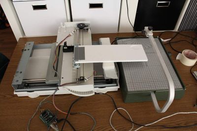
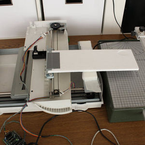
The lightscanner has some advantages: It consists of 2 stepper motors and rails which are synchronized. That means that the steps per axis are equal, so we don't have to compensate in order to plot some correct circles.
The internal electronics of the scanner were removed and the light unit was sawed to an appropiate size and was fixed across the slide of the scanner with two screws. Using Plaast, an angle bracket was attached to the slide to keep the styrofoam in place.
After reverse engineering the steppers by "trial and error" and measuring the resistors, they could be easily attached to the motorshield.
Software
Arduino (with Motor Shield)
The arduino receives bit-encoded data from processing via the serial interface. Bit 1/2 controls the x-Axis and bit 3/4 the y-Axis So if you want to move the plotting position to x+1 and y-1, processing sends a decimal 9 to the arduino
| 0001: | y0, | x+ | (1) | |
| 0010: | y0, | x- | (2) | |
| 0100: | y+, | x0 | (4) | |
| 1000: | y-, | x0 | (8) | |
| 0101: | y+, | x+ | (5) | |
| 0110: | y+, | x- | (6) | |
| 1010: | y-, | x- | (10) | |
| 1001: | y-, | x+ | (9) |
Here is the arduino code:
#include <AFMotor.h>    //http://www.ladyada.net/make/mshield/download.html
                        //https://github.com/adafruit/AccelStepper

AF_Stepper motor1(200, 2);
AF_Stepper motor2(200, 1);

int byte_in;         // variable to store the VALID data from the port
char nextMsg;


void setup(){

  motor1.setSpeed(50);  // in rpm
  motor2.setSpeed(50);  // in rpm

  Serial.begin(9600);
  digitalWrite(13, HIGH); //turn on LED to indicate program has started
}

void loop(){

  if(Serial.available() > 0){
    byte_in = Serial.read(); //read the serial buffer
    Serial.flush(); //empty serial buffer
    if (byte_in != -1){ //if anything was received...
            decodeMessage(byte_in);
    }
  }
}

void decodeMessage(int msg){

  int faktor = 5;
  //check command type and command value
  //read bits and move appropriate stepper
  if(bitRead(msg, 0) == 1){
    //Bit 1 = High   DOWN (1)
    motor1.step(faktor, FORWARD, INTERLEAVE);
  }
  if(bitRead(msg, 1) == 1){
    //Bit 2 = High   UP (2)
    motor1.step(faktor, BACKWARD, INTERLEAVE);
  }
  if(bitRead(msg, 2) == 1){
    //Bit 3 = High   LEFT (4)
    motor2.step(faktor, FORWARD, INTERLEAVE);
  }
  if(bitRead(msg, 3) == 1){
    //Bit 4 = High   RIGHT (8)
    motor2.step(faktor, BACKWARD, INTERLEAVE);
  }
  sendMsg(000); //send a message back for testing purposes
}

void sendMsg(int msg){

  if(Serial.available() > 0) Serial.flush();
  Serial.print(9999); //...send a confirmation
}
Processing
The processing of the svg files is done by Geomerative-Libary. The library writes the data of the line into an array which is processed point by point in the following step.
As the arduino only understands relative movements which are expressed as points in each direction the lines are interpolated with the Bresenham-Algorithm.
You can download the sourcecode from github here: https://github.com/ptflea/Styroplotter -> StyroPlotter_proc.pde
Plot-Data
Processing reads the SVG files which were created with Inkspcape. The Styroplotter needs svg paths which run into one direction. To show the directions of the paths in inkscape you have to set the following preferences:
File -> Inkscape-Preferences -> Node
Check "Show path direction on outline" option. Now the paths should have small red arrows on them.
It's important that you pay attention to the direction of the paths -- otherwise, the path will look fine, but the styroplotter will interrupt and look for a place from which the direction is right. (The way it runs can be simulated in the processing code by commenting out the parts that send commands to the Arduino chip.)
You can find a cluttered directory of svg files on github in the data/ directory: https://github.com/ptflea/Styroplotter
Action
|
Styroplotter in Action VIDEO
|
Styroplotter cutting pacman VIDEO |
Results
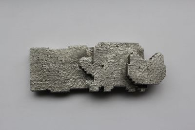
| And that is how the NyanCat looks like in Aluminum: |

